"Everybody is a genius. But if you judge a fish by its ability to climb a tree, it will live its whole life believing that it is stupid."Einstein
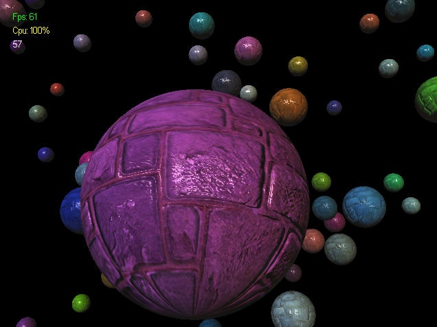
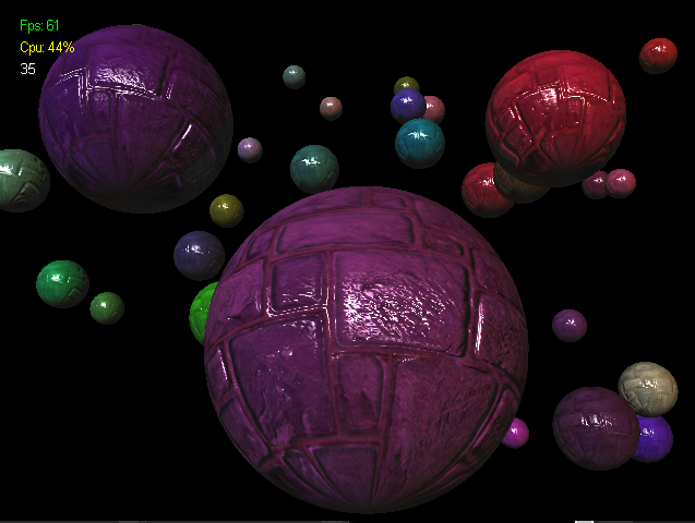
Tiny DirectX11 Application
I’m extending my journey into graphics renderering by DirectX11. I found this larger collection of tutorials and I will go through them as far as possible. I’ll report here my findings and the most important points IMHO.
Creating A Framework and Window
Missing description of long intialization.
Basic Initialization Of DirectX11
1
2
3
4
5
6
7
8
9
// COM interface object used to change the back to the front buffer
IDXGISwapChain* SwapChain;
// interface, which represents our hardware device (GPU)
ID3D11Device* d3d11Device;
//  2nd part of device interface, used to call rendering methods
ID3D11DeviceContext* d3d11DevCon;
// interface object which is the render target view
//  we write into this 2D texture and this texture is sent to the pipeline
ID3D11RenderTargetView* renderTargetView;
Create the Swap Chain, the Back Buffer and the Render Target View. Actually we write into the 2D texure of the Render Target View and send this to the pipeline to be rendered. Then bind them to the Output-Merger State of the pipeline.
1
2
3
4
5
6
7
8
9
10
11
12
13
14
15
16
17
18
19
20
21
22
23
24
25
26
27
28
29
30
31
32
33
34
35
36
37
38
39
// Create SwapChain
hr = D3D11CreateDeviceAndSwapChain(
  NULL,                     // pAdapter
  D3D_DRIVER_TYPE_HARDWARE, // DriverType
  NULL,                     // Software
  NULL,                     // Flags
  NULL,                     // pFeatureLvls
  NULL,                     // FeatureLvls
  D3D11_SDK_VERSION,        // SDK Version
  &swapChainDesc,           // pSwapChainDesc
  &SwapChain,               // ppSwapChain Interface
  &d3d11Device,             // ppDevice
  NULL,                     // pFeatureLvls
  &d3d11DevCon              // ppImmediateContext
  );

// Create BackBuffer
ID3D11Texture2D* BackBuffer;
hr = SwapChain->GetBuffer(
  0,                            // first buffer
  __uuidof( ID3D11Texture2D ),  // ref ID to type of interface
  (void**)&BackBuffer           // ptr to buffer
  );

// Create Render Target
hr = d3d11Device->CreateRenderTargetView(
  BackBuffer,        // pResource
  NULL,              // pDesc
  &renderTargetView  // pRTView
  );
// we don't need the backbuffer anymore
BackBuffer->Release();

// Bind  Render Target to Output-Merger state
d3d11DevCon->OMSetRenderTargets(
  1,                 // NumViews of render target views
  &renderTargetView, // ppRenderTargetViews
  NULL               // pDepthStencilView
  );
Rendering A Scene
1
2
3
4
5
6
7
8
9
10
11
12
13
14
15
16
void DrawScene()
{
  // clear backbuffer to color
  D3DXCOLOR bgColor(red, green, blue, 1.f);

  d3d11DevCon->ClearRenderTargetView(
    renderTargetView,  // pRenderTargetView
    bgColor            // ColorRGBA
    );

  // present backbuffer to screen
  SwapChain->Present(
    0,                 // SyncInterval
    0                  // Flags
    );
}
Spaces
Local Space
Local space is the space relative to an object.
World Space
World space is used to position each object relative to eatch other, in the world space.
View Space
The view space is basically the camera’s space.
Projection Space
The space that, if objects are in, they are rendered to the screen, and if objects are out, they are discarded. It is defined by six planes, the near plane, far plane, top, left, bottom and right planes.
Screen Space
The last space is basicallz the x and y values in pixels of the backbuffer, where marks the top left of the space. This is the 2D space thats actually displayed on the monitor.
Matrices
The rendering pipeline uses three spaces: World, View and Projection. To transform them from one to the other, we will multiply them together.
World Matrix
This matrix is used to convert the vertices of our objects into vertices in the 3D scene.
View Matrix
The view matrix is used to calculate the position of where we are looking at the scene from.
Projection Matrix
The projection matrix is used to translate the 3D scene into the 2D viewport space.
Orthographic Projection Matrix
This matrix is used for rendering 2D element like user interfaces on the screen allowing us the skip the 3D rendering.
Buffers
Vertex Buffer
An objects is composed of hundreds of triangles. Each of the triangles in the model has three points to it, they re called vertices. To render the object we need to put all vertices into a special array that we call vertex buffer.
Input Layout
Direct3D uses what is called an input layout. An input layout is the layout of the data containing the location and properties of a vertex.
Input layout let us select which information we want to use and send just that data. This enables us to send many more vertices between each frame.
1
2
3
4
5
6
7
8
9
10
11
12
13
14
15
16
17
18
19
20
// create the vertex input layout description
// this setup needs to match the VERTEXTYPE structure in the vertexbuffer and shader
polygonLayout[0].SemanticName = "POSITION";
polygonLayout[0].SemanticIndex = 0;
polygonLayout[0].Format = DXGI_FORMAT_R32G32B32A32_FLOAT;
polygonLayout[0].InputSlot = 0;
polygonLayout[0].AlignedByteOffset = 0;
polygonLayout[0].InputSlotClass = D3D11_INPUT_PER_VERTEX_DATA;
polygonLayout[0].InstanceDataStepRate = 0;

polygonLayout[1].SemanticName = "TEXCOORD";
polygonLayout[1].SemanticIndex = 0;
polygonLayout[1].Format = DXGI_FORMAT_R32G32_FLOAT;
polygonLayout[1].InputSlot = 0;
polygonLayout[1].AlignedByteOffset = D3D11_APPEND_ALIGNED_ELEMENT;
polygonLayout[1].InputSlotClass = D3D11_INPUT_PER_VERTEX_DATA;
polygonLayout[1].InstanceDataStepRate = 0;

/* and other layuouts */
// ...
1
2
3
4
5
6
7
8
// create the vertex input layout
result = device->CreateInputLayout(
  polygonLayout,
  numElements,
  vertexShaderBuffer->GetBufferPointer(),
  vertexShaderBuffer->GetBufferSize(),
  &m_layout
  );
The input layout is set in the input assembler stage of the render pipeline.
1
2
// set the vertex input layout
deviceContext->IASetInputLayout(m_layout);
Index Buffers
Index buffers are related to vertex buffers. Their purpose is to record the location of each vertex that is in the vertex buffer. They help find the vertex faster.
Vertex Shaders
Vertex shaders are small programms that are written maily for transforming the vertices from the vertex buffer into 3d space.
1
2
3
4
5
struct VertexType
{
  XMFLOAT3 position;
  XMFLOAT2 texture;
};
1
2
3
4
5
6
7
8
9
10
11
12
13
14
VertexType* vertices;

// load the vertex array data
vertices[0].position = XMFLOAT3(-1.f, -1.f, 0.f); // bottom left
vertices[0].texture = XMFLOAT2(0.f, 1.f);

vertices[1].position = XMFLOAT3(-1.f, 1.f, 0.f);  // top left
vertices[1].texture = XMFLOAT2(0.f, 0.f);

vertices[2].position = XMFLOAT3(1.f, 1.f, 0.f);   // top right
vertices[2].texture = XMFLOAT2(1.f, 0.f);

vertices[3].position = XMFLOAT3(1.f, -1.f, 0.f);  // bottom right
vertices[3].texture = XMFLOAT2(1.f, 1.f);
1
2
3
4
5
6
7
8
9
10
11
// set up the description of the static vertex buffer
vertexBufferDesc.Usage = D3D11_USAGE_DEFAULT;
vertexBufferDesc.ByteWidth = sizeof(VertexType) * m_vertexCount;
vertexBufferDesc.BindFlags = D3D11_BIND_VERTEX_BUFFER;
vertexBufferDesc.CPUAccessFlags = 0;
vertexBufferDesc.MiscFlags = 0;
vertexBufferDesc.StructureByteStride = 0;
// give the subresource structure a pointer to the VERTEX DATA
vertexData.pSysMem = vertices;
vertexData.SysMemPitch = 0;
vertexData.SysMemSlicePitch = 0;
1
2
3
4
5
6
// now create the vertex buffer
result = device->CreateBuffer(
  &vertexBufferDesc,    // ptr to buffer description
  &vertexData,          // ptr to subresource data structure
  &m_vertexBuffer       // returned ID3D11 buffer
  );
Pixel Shaders
Pixel shaders are small programs that are written for doing the coloring of the polygons that we draw. They are run by the GPU for every visible pixel.
Constant Buffers
A constant buffer is basically a structure in an effect file which holds variables able to be updated from the game code. It can be created using the cbuffer type.
1
2
3
4
5
6
7
8
//
// Vertex Shader
cbuffer MatrixBuffer
{
  matrix worldMatrix;
  matrix viewMatrix;
  matrix projectionMatrix;
};
1
2
3
4
5
6
7
8
9
10
11
12
13
14
15
16
17
18
19
20
21
22
23
24
25
26
27
28
29
//
// Game Code

// direct3D buffer interface
ID3D11Buffer* m_matrixBuffer;

// constant buffer structure
struct MatrixBufferType
{
  XMMATRIX world;
  XMMATRIX view;
  XMMATRIX projection;
};
MatrixBufferType matrices;

// setup the description of the constant buffer
matrixBufferDesc.Usage = D3D11_USAGE_DEFAULT;
matrixBufferDesc.ByteWidth = sizeof(MatrixBufferType);
matrixBufferDesc.BindFlags = D3D11_BIND_CONSTANT_BUFFER;
matrixBufferDesc.CPUAccessFlags = 0;
matrixBufferDesc.MiscFlags = 0;
matrixBufferDesc.StructureByteStride = 0;

// create the constant buffer ptr
result = device->CreateBuffer(
  &matrixBufferDesc,  // buffer description
  NULL,               // pInitialData
  &m_matrixBuffer     // ptr to buffer interface
  );
Update The Constant Buffer
Important: When sending matrices to the effect file in direct3D 11, they must be transposed.
1
2
3
4
5
6
7
8
9
10
11
12
13
14
15
16
17
18
19
20
21
22
23
24
25
26
27
28
29
//
// Game Code

// transpose the matrices to prepare them for the shader
matrices.world =
  XMMatrixTranspose(worldMatrix);
matrices.view =
  XMMatrixTranspose(viewMatrix);
matrices.projection =
  XMMatrixTranspose(projectionMatrix);

deviceContext->UpdateSubresource(
  m_matrixBuffer,   // pDestResource
  0,                // DstSubResource
  NULL,             // pDstBox
  &cbMatrices,      // pSrcData
  0,                // SrcRowPitch
  0                 // SrcDepthPitch
  );

// set the position of the constant buffer in the vertex shader
bufferNumber = 0;

// finally set the constant buffer in the vertex shader with the updated values
deviceContext->VSSetConstantBuffers(
  bufferNumber,
  1,
  &m_matrixBuffer
  );
Shaders And HLSL
The vertex and pixel shader are COM objects.
1
2
3
4
5
6
7
8
9
10
11
12
13
14
15
16
17
18
19
// global
ID3D11VertexShader* pVS;
ID3D11PixelShader* pPS;

void InitPipeline()
{
  // load and compile the two shaders
  ID3D10Blob *VS, *PS;
  D3DX11CompileFromFile(L"shaders.shader", 0, 0, "VShader", "vs_4_0", 0, 0, 0, &VS, 0, 0);
  D3DX11CompileFromFile(L"shaders.shader", 0, 0, "PShader", "ps_4_0", 0, 0, 0, &PS, 0, 0);

  // encapsulate both shaders into shader objects
  dev->CreateVertexShader(VS->GetBufferPointer(), VS->GetBufferSize(), NULL, &pVS);
  dev->CreatePixelShader(PS->GetBufferPointer(), PS->GetBufferSize(), NULL, &pPS);

  // set the shader objects
  devcon->VSSetShader(pVS, 0, 0);
  devcon->PSSetShader(pPS, 0, 0);
}
Programmable Graphics Rendering Pipeline
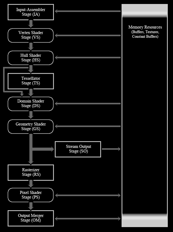
Input Assembler (IA)
The IA is a fixed function stage, which reads geometric data, vertices and indices. It uses the data to create primitives which will be fed into and used by other stages. The two buffers used by the IA are the vertex and index buffers.
Vertex Shader (VS)
The VS is the first programmable shader, which means we have to program it ourselves. The VS stage is what all the vertices go through after the primitives have been assembled in the IA. It allows transformation, scaling, lighting, displacement mapping for textures and stuff like that.
The vertex shader takes a single vertex as input and returns a single input.
Hull Shader (HS)
The HS is the first of the three optional stages added to graphics rendering pipeline. The three new stages , Hull Shader, Tessellator and Domain Shader, all work together to implement tesselation.
Tesselation takes a primitive object and divides it up into many smaller section to increase the detail of models. They are not saved to memory, so this saves much time in creating them on the CPU and memory.
The Hull Shader calculates how and where to add new verties to a primitive to make it more detailed.
Tessellator (TS)
The TS is the second, fixed stage in the tessellation process and actually does the diving of the primitive.
Domains Shader (DS)
This programmable function stage transforms the vertices from the the tessellator stage to create the more detail.
Geometry Shader (GS)
Another optional pragrammable function stage. It is able to create or destroy primitives.
Stream Output (SO)
This stage is used to obtain Vertex data from the pipeline. Vertex data output from the SO are always sent out as lists, such as line lists or triangle list. Incomplete primitives are never sent out, they are just silently discarded.
Rasterization Stage (RS)
The RS stage takes the vector information sent to it and turns them into pixels by interpolating per-vertex values across each primitive. It also handles the clipping.
Pixel Shader (PS)
This stage does calculations and modifies each pixel, such as lighting on a per pixel base. It is another programmable function and an optional stage.
The job of the pixel shader is to calculate the final color of each pixel fragment.
Output Merger (OM)
The final stage in the pipeline. This stage takes the pixel fragments and depth/stencil buffers and determines which pixels are actually written to the render target.
Depth/Stencil View
This lets the OM stage check all the pixel fragment’s depth/stencil values on a render target. The depth values are used to draw pixel which are in front and discard those in the back. The stencila part of the depth view is for advanced techniques, such as mirrors.
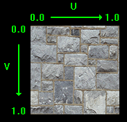
Texturing
To map pixels from a texture file onto the polygo the Texel Coordinate system is to be used. This system converts the integer value of the pixel into a floating point value between 0.f and 1.f.
In the texel coordinate system the width value is named U and the height value is named V. The width goes from 0.0 on the left to 1.0 on the right. The height goes from 0.0 on the top to 1.0 on the bottom.
Copy Data Into Textures
Using Map and Unmap is generally a lot quicker than using UpdateSubresource. The recommendation is to use Map and Unmap for data that is going to be reloaded each frame or on a very reular basis. And to use UpdateSubresource for something that will be loaded once or that gets loaded rarely during loading sequences.
Example: Copying Matrices To Vertex Shaders
This procedure is also usable in case of copying light data, such as diffuse color, light direction and likewise.
1
2
3
4
5
6
7
// must match the cbuffer from VS
struct MatrixBufferType
{
  XMMATRIX world;
  XMMATRIX view;
  XMMATRIX projection;
};
1
2
3
4
5
6
7
8
9
10
11
12
13
14
15
16
17
18
19
20
21
22
23
24
25
26
HRESULT result;
D3D11_MAPPED_SUBRESOURCE mappedResource;
MatrixBufferType* dataPtr;

// lock the constant buffer so it can be written to
result = deviceContext->Map(
  m_matrixBuffer,
  0,
  D3D11_MAP_WRITE_DISCARD,
  0,
  &mappedResource
  );

// get a pointer to the data in the constant buffer
dataPtr = (MatrixBufferType*)mappedResource.pData;

// copy the matrices into the constant buffer
dataPtr->world = worldMatrix;
dataPtr->view = viewMatrix;
dataPtr->projection = projectionMatrix;

// unlock the constant buffer
deviceContext->Unmap(
  m_matrixBuffer,
  0
  );
1
2
3
4
5
6
7
8
9
10
11
12
13
14
15
16
// set the position of the constant buffer in the vertex shader
bufferNumber = 0;

// now set the constant buffer in the vertex shader with the updated values
deviceContext->VSSetConstantBuffers(
  bufferNumber,
  1,
  &m_matrixBuffer
  );

// set shader texture resoure in pixel shader
deviceContext->PSSetShaderResources(
  0,
  1,
  &texture
  );
Sampler State
Sampler State determines how texture data is sampled using texture addressing modes, filtering and level of detail. The texture coordinates are used to address a texel (texture pixel) when samping a texture.
We have to create, define a sampler state and pass it over to the Pixel Shader.
1
2
3
4
5
6
7
8
9
10
11
12
13
14
// create a texture sampler state description
sDesc.Filter = D3D11_FILTER_MIN_MAG_MIP_LINEAR;	// filter method
sDesc.AddressU = D3D11_TEXTURE_ADDRESS_WRAP;    // behavior if U is larger than 1 or less than 0
sDesc.AddressV = D3D11_TEXTURE_ADDRESS_WRAP;    // behavior if V is larger than 1 or less than 0
sDesc.AddressW = D3D11_TEXTURE_ADDRESS_WRAP;    // behavior if W is larger than 1 or less than 0
sDesc.MipLODBias = 0.f;      // offset from calculated mipmap level
sDesc.MaxAnisotropy = 1;     // filter
sDesc.ComparisonFunc = D3D11_COMPARISON_ALWAYS; // compare mipmap data with another mipmaps sampled data for this texture
sDesc.BorderColor[0] = 0;
sDesc.BorderColor[1] = 0;
sDesc.BorderColor[2] = 0;
sDesc.BorderColor[3] = 0;
sDesc.MinLOD = 0;            // lowest mipmap level (0=most detailed and largest)
sDesc.MaxLOD = D3D11_FLOAT32_MAX;  // largest mipmap level (0=most detailed and largest)
1
2
3
4
5
// create the texture sampler state
result = device->CreateSamplerState(
  &samplerDesc,
  &m_sampleState
  );
1
2
3
4
5
6
// set the sampler state in the pixel shader
deviceContext->PSSetSamplers(
  0,                // start slot
  1,                // number of samplers
  &m_sampleState    // sampler
  );
Lighting
Different lighting concept are used to implemente basic lighting effects. These includes ambient, diffuse and specular light. This link gives a closer look to the background of this basic shading concepts.
Most of this concepts happens in the pixel shader and some pre-calculations in the vertex shader.
We have to create two structures to pass data to the shaders, the LightBufferType and the CameraBufferType.
1
2
3
4
5
6
7
8
9
10
11
12
13
14
struct LightBufferType
{
  XMVECTOR ambientColor;
  XMVECTOR diffuseColor;
  XMFLOAT3 lightDirection;
  float specularPower;
  XMVECTOR specularColor;
};

struct CameraBufferType
{
  XMFLOAT3 cameraPosition;
  float padding;  // needed to fullfil the 16bit arrangement
};
These constant buffers are mapped to the constant buffers in the shaders. Similar what happens to the matrix buffer (world matrix, view matrix, projection matrix).
1
2
3
4
5
6
7
8
9
10
11
12
13
14
15
16
17
18
19
20
21
22
23
24
25
26
27
28
29
30
31
32
33
34
35
36
37
38
39
40
41
42
// lock the camera constant buffer so it can be written to
result = deviceContext->Map(
  m_cameraBuffer,
  0,
  D3D11_MAP_WRITE_DISCARD,
  0,
  &mappedResource
  );

// get a pointer to the data in the constant buffer
dataPtr3 = (CameraBufferType*)mappedResource.pData;

// copy the camera position into the constant buffer
dataPtr3->cameraPosition = cameraPosition;
dataPtr3->padding = 0.f;

// unlock the camera constant buffer
deviceContext->Unmap(
  m_cameraBuffer,
  0
  );


// set the position of the camera constant buffer in the vertex shader
bufferNumber = 1;

// now set the camera constant buffer in the VERTEX shader with the updated values
deviceContext->VSSetConstantBuffers(
  bufferNumber,
  1,
  &m_cameraBuffer
  );

/* Same for the light buffer
   ...
*/
// finally set the light constant buffer in the PIXEL shader with the updated values
deviceContext->PSSetConstantBuffers(
  bufferNumber,
  1,
  &m_lightBuffer
  );
Since we passed now the data the shaders we can used it there.
Inside The Shaders
Create the constant buffers to receive the data from the CPU.
1
2
3
4
5
6
7
8
9
10
11
12
13
14
15
16
17
18
19
20
21
22
23
24
25
26
27
28
29
30
31
32
33
34
35
36
37
// VERTEX shader's constant buffers
cbuffer CameraBuffer
{
  float3 cameraPosition;
  float padding;
};

// output to PIXEL shader
struct PixelInputType
{
  float4 position : SV_POSITION;
  float2 tex : TEXCOORD0;
  float3 normal : NORMAL;
  float3 viewDirection : TEXCOORD1;  // calculated from the camera position
};

//
// Vertex Shader
PixelInputType LightVertexShader(VertexInputType input)
{
  PixelInputType output;
  float4 worldPosition;

  /* ... */

  // calculate the position of the vertex in the world
  worldPosition = mul(input.position, worldMatrix);

  // determine the viewing direction based on the position of the camera
  //  and the position of the vertex in the world
  output.viewDirection = cameraPosition.xyz - worldPosition.xyz;

  // normalize the viewing direction vector
  output.viewDirection = normalize(output.viewDirection);

  return output;
}
Finally in the pixel shader happens all the magic (lighting). First we need again a constant buffer to accept the data from the CPU and secondly an input struct to receive the data from the vertex shader.
1
2
3
4
5
6
7
8
9
10
11
12
13
14
15
16
cbuffer LightBuffer
{
  float4 ambientColor;
  float4 diffuseColor;
  float3 lightDirection;
  float specularPower;
  float4 specularColor;
};

struct PixelInputType
{
  float4 position : SV_POSITION;
  float2 tex : TEXCOORD0;
  float3 normal : NORMAL;
  float3 viewDirection : TEXCOORD1;
};
And now the magic..
1
2
3
4
5
6
7
8
9
10
11
12
13
14
15
16
17
18
19
20
21
22
23
24
25
26
27
28
29
30
31
32
33
34
35
36
37
38
39
40
41
42
43
44
45
46
47
48
49
50
51
52
53
//
// pixel shader
float4 LightPixelShader(PixelInputType input) : SV_TARGET
{
  float4 textureColor;
  float3 lightDir;
  float lightIntensity;
  float4 color;
  float3 reflection;
  float4 specular;

  // sample the pixel color from the texture using the sampler
  //  at this texture coord location
  textureColor = shaderTexture.Sample(SampleType, input.tex);

  // set the default output colot to the ambient light value for all pixels
  color = ambientColor;

  // initialize the specular color
  specular = float4(0.f, 0.f, 0.f, 0.f);

  // invert the light direction for calculations
  lightDir = -lightDirection;

  // calculate the amount of light on this pixel
  lightIntensity = saturate(dot(input.normal, lightDir));	// saturate clamps values within range of 0 to 1
  if (lightIntensity > 0.f)
  {
    // determine the final amount of diffuse color based on the
    //  diffuse color combined with the light intensiy
    color += (diffuseColor * lightIntensity);

    // saturate the ambient and diffuse color
    color = saturate(color);

    // calculate the reflection vector based on the light intensity, normal vector and light direction
    //  walk twice the lightIntensity in the direction of input.normal and subtract
    //  the light direction l to get the reflection vector r
    reflection = normalize(2 * lightIntensity * input.normal - lightDir);

    // determine the amount of specular light based on the
    //  reflection vector, viewing direction and specular power
    specular = pow(saturate(dot(reflection, input.viewDirection)), specularPower);
  }

  // Multiply the texture pixel and the input color to get the textured result.
  color = color * textureColor;

  // Add the specular component last to the output color.
  color = saturate(color + specular);

  return color;
}
2D Rendering aka Sprites
2D overlays such as text or program information which are not related to the 3D world are displayed by an orthographic projection.
The information is displayed as texture on a polygon. The keep the information on the screen, the vertices have to be updated dynamically. This is achieved by using dynamic vertex buffers instead of static vertex buffers.
To make it dynamic we set Usage to D3D11_USAGE_DYNAMIC and CPUAccessFlags to D3D11_CPU_ACCESS_WRITE in the description.
1
2
3
4
5
6
7
8
9
10
11
12
13
14
15
16
17
18
19
// set up the description of the DYNAMIC VERTEX BUFFER
vertexBufferDesc.Usage = D3D11_USAGE_DYNAMIC;
vertexBufferDesc.ByteWidth = sizeof(VertexType) * m_vertexCount;
vertexBufferDesc.BindFlags = D3D11_BIND_VERTEX_BUFFER;
vertexBufferDesc.CPUAccessFlags = D3D11_CPU_ACCESS_WRITE;
vertexBufferDesc.MiscFlags = 0;
vertexBufferDesc.StructureByteStride = 0;

// give the subresource structure a pointer to the vertex data
vertexData.pSysMem = vertices;
vertexData.SysMemPitch = 0;
vertexData.SysMemSlicePitch = 0;

// now create the vertex buffer
result = device->CreateBuffer(
  &vertexBufferDesc,
  &vertexData,
  &m_vertexBuffer
  );
Z-Buffer
The Depth/Stencil State Description has a parameter to enable or disable the depth handling.
1
2
3
4
5
6
7
8
9
10
11
12
13
ID3D11DepthStencilState* m_depthDisabledStencilState;
D3D11_DEPTH_STENCIL_DESC depthDisabledStencilDesc;

// create a depth stencil state which turns off the Z Buffer
//  e.g. for 2D rendering
depthDisabledStencilDesc.DepthEnable = false;  // true
/* ... */

// create the state using the device
result = m_device->CreateDepthStencilState(
  &depthDisabledStencilDesc,			// description
  &m_depthDisabledStencilState		// stencil state
  );
To switch between activated and disabled depth buffering, e.g. for 2D rendering, a second depth/stencil state description is needed. Passing the corresponding state to the Output Merger State (OM) controls the depth buffering.
1
2
3
4
m_deviceContext->OMSetDepthStencilState(
  m_depthDisabledStencilState,   // depth/stencil state
  1                              // stencil reference
  );
To Remember
The Output Merger State determines which pixels are actually written to the render target.
Font
Writing text onto the screen is a pretty important function of any application. It is done in DirectX 11 by rendering 2D images. The font is stored in a DDS texture and access from the font engine by cutting out a square (two triangels) and render the content of the texture (font) to a bitmap.
Blending
The Blend State Decription has a parameter to enable or disable the blening.
1
2
3
4
5
6
7
8
9
10
11
12
D3D11_BLEND_DESC blendStateDesc;
ID3D11BlendState* m_alphaEnableBlendingState;

// create an ALPHA ENABLED state description
blendStateDesc.RenderTarget[0].BlendEnable = TRUE;
/* ... */

// create the blend state using the description
result = m_device->CreateBlendState(
  &blendStateDesc,
  &m_alphaEnableBlendingState
  );
To switch between alpha blending, e.g. for writing font, a second blend state description is needed. Passing teh corresponding state to the Output Merger State (OM) controls the alpha blending.
1
2
3
4
5
6
7
8
9
10
11
12
13
14
float blendFactor[4];

// set up the blend factor
blendFactor[0] = 0.f;
blendFactor[1] = 0.f;
blendFactor[2] = 0.f;
blendFactor[3] = 0.f;

// turn on the alpha blending
m_deviceContext->OMSetBlendState(
  m_alphaEnableBlendingState,  // blend state
  blendFactor,                 // blend factor
  0xFFFFFFFF                   // sample mask
  );
Alpha Blending
Alpha blending is a convex combination of two colors allowing for transparency effects in computer graphics. Alpha Blending is the process of combining a translucent foreground color wiht ha background color, thereby producing a new blended color.
Frustum Culling
Frustum culling helps to reduce the calculation of not drawn object.
Frustum
We calculate the frustum’s plane near, far, left, right, up, down by means of trigonometry. This paper describes the math behind it.
By means of the frustum we then can check, prior of rendering the objects, if they lie in the frustum or not. This is in the current approach done on the CPU.
Multitexturing And Texture Arrays
Multitexturing is the process of blending two different textures to create a final texture. The equation you use to blend two textures can differ depending on the result you are trying to achieve.
Texture Arrays is a new feature since DirectX 10 that allows you to have multiple textures active at once in the gpu.
First, create a Shader Resource Array containing both loaded textures.
1
2
3
4
5
6
7
8
9
10
11
12
13
14
15
16
17
ID3D11ShaderResourceView* m_textureArray[2];

// load the first texture in
result = DirectX::CreateDDSTextureFromFile(
  device,
  filename1,
  NULL,
  &m_textureArray[0]
);

// load the second texture in
result = DirectX::CreateDDSTextureFromFile(
  device,
  filename2,
  NULL,
  &m_textureArray[1]
);
Then all that is to be done is to pass this array of textures to the Pixel Shader.
1
2
3
4
5
6
// set shader texture resoure in pixel shader
deviceContext->PSSetShaderResources(
  0,            // start slot
  2,            // number of textures in the array
  textureArray  // texture resource array [2]
);
Finally in the Pixel Shader the two textures are combined to the final color.
1
2
3
4
5
6
7
8
9
10
11
12
13
14
15
16
17
18
19
20
21
22
23
24
25
26
27
28
29
Texture2D shaderTexture[2];
SamplerState SampleType;
/* ... */

//
// pixel shader
float4 PixelShader(PixelInputType input) : SV_TARGET
{
  float4 textureColor1;
  float4 textureColor2;
  /* ... */
  float4 color;

  // sample the pixel color from the texture using the sampler
  //  at this texture coord location
  textureColor1 = shaderTexture[0].Sample(
    SampleType,
    input.tex
  );
  textureColor2 = shaderTexture[1].Sample(
    SampleType,
    input.tex
  );

  color = textureColor1 * textureColor2 * 2.0;
  color = saturate(color);

  return color;
}
Light Maps
Light map are a cheap but static alternative to light calculations. They are achieved by using Multitexturing with an additional light map.
In the Pixel Shader it’s possible to adjust the intensity of the multitexturing to create different light effects.
Alpha Maps
The realization of alpha maps is highly related to Multitexturing and light maps. Two merge two textures from one to the other, an additional textures is passed to the pixel shader. This texure contains a black/white/alpha value in the style how the to textures should merge.
In the pixel shader the alpha map is used to calculate the color of the current pixel by using:
1
2
3
4
5
6
7
8
9
10
11
12
13
14
15
16
17
float PixelShader(PixelInputType input) : SV_TARGET
{
  float4 textureColor1;
  float4 textureColor2;
  float4 alphaValue;
  float4 blendTexColor;

  // sample the pixel color from the texture using the sampler
  //  at this texture coord location
  textureColor1 = shaderTexture[0].Sample(SampleType, input.tex);
  textureColor2 = shaderTexture[1].Sample(SampleType, input.tex);
  alphaValue    = shaderTexture[2].Sample(SampleType, input.tex);

  // combine the two textures based on the alpha value
  blendTexColor = (alphaValue * textureColor1) + ((1.0 - alphaValue) * textureColor2);
  blendTexColor = saturate(blendTexColor);
}
Bump Mapping
The proper terminology for the bump mapping technique explained here is called normal mapping. The reason being is that here a special texture called a normal map is used to loop up the surface normals.
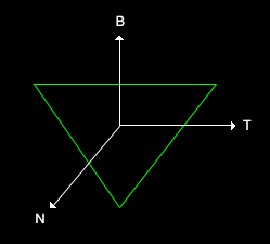
The binormal and tangent vector are to be determined at each pixel. This creates the local coordinate system in which the bump normal can be calculated by means of the bump map.
Tangent & Binormal Calculation
This two vectors are calculated within the CPU. The two vectors are the coordination vectors from the UV texture transferred into Modelspace.
This transformation is better explained here.
The bumpmap represents the normal vectors in the modelspace for each pixel as a texture. Multiplying them with the unit vector of the above calculated coordinate system results in the actually normal vectors to be used in the lighting calculations.
After the following calculation the new normal for each pixel can be used for the final result.
This calculation can be done during model loading or stored in the model format. This should never be done in the shader due to fairly expensive floating point math.
The outcome looks like this:
Specular Mapping
Additionally to the above described process of bumpmapping, in specular mapping a grey scale map is used to determine the intensity of specular light at each pixel.
The calculation for the reflection remains the same as in the reflection model. Now the amount of specular light is multiplied by the specular intensity defined in the specular map.
In the following image a specular map has been added to the existing model.