"It’s not that I’m so smart, it’s just that I stay with problems longer."Einstein
Graphic Pipeline - An Introduction
Back in 2016 I found this little tutorial about the programming of a renderer. Due to other projects I could fullfil this one. And this is why I’m back on it.
I love seeing computer creating virtual worlds and therefore I want to now what are the basics of it.
With this little tutorial created by Jofrey Luc I try to fill this mind gap. The goal is to build a small “tiny” renderer powered by the CPU.
I will document my humble opinion and what I learnt from it here in this posts.
Homogeneous Coordinates
The basis for computer graphics is suited in the approach of Affin transformation and results in the used of homogeneous coordinates. This link describes a mathematical view of the used method.
Modelview Matrix
Due to the camera position the new coordinate system of the objects has to be calculated.
Chain Of Coordinate Transformation
Our models, e.g. characters, are created in their own local frame (object coordinates). They are inserted into a scene expressed in world coordinates. The transformation from one to another is made with matrix Model. Then, we want to express it in the camera frame (eye coordinates), the transformation is called View. Then, we deform the scene to create a perspective deformation with Projection matrix. This matrix transforms the scene to so-called clip coordinates. Finally, we draw the scene, and the matrix transforming clip coordinates to the screen coordinates is called Viewport.
Example
A point from the .obj file undergoes the following chain of transformation:
LookAt Method
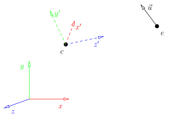
The lookAt method calculates the ModelView matrix by means of the eye, its up vector and the center coordinates. With this three vectors we can calculate the inverse transformation matrix from the initial coordinate system to the model coordinate system.
1
2
3
4
5
6
7
8
9
10
11
12
13
14
void lookat(Vec3f eye, Vec3f center, Vec3f up) {
    Vec3f z = (eye-center).normalize();
    Vec3f x = cross(up,z).normalize();
    Vec3f y = cross(z,x).normalize();
    Matrix Minv = Matrix::identity();
    Matrix Tr   = Matrix::identity();
    for (int i=0; i<3; i++) {
        Minv[0][i] = x[i];
        Minv[1][i] = y[i];
        Minv[2][i] = z[i];
        Tr[i][3] = -center[i];
    }
    ModelView = Minv*Tr;
}
Viewport Matrix
The viewport matrix maps a bi-unit square onto the image (screen). It means that the bi-unit cube $[-1,1] * [-1,1] * [-1,1]$ is mapped onto the screeen cube $[x, x+w]*[y, y+h] * [0, d]$. A cube and not a rectangle, this is because of the depth computations with the z-buffer.
1
2
3
4
5
6
7
8
9
10
11
Matrix viewport(int x, int y, int w, int h) {
    Matrix m = Matrix::identity(4);
    m[0][3] = x+w/2.f;
    m[1][3] = y+h/2.f;
    m[2][3] = depth/2.f;

    m[0][0] = w/2.f;
    m[1][1] = h/2.f;
    m[2][2] = depth/2.f;
    return m;
}
Transformation Of Normal Vectors
If we have a model and its normal vectors are given by the artist AND this model is transformed with an affine mapping, then normal vectors are to be transformed with a mapping, equal to the transposition of the inverse matrix of the original mapping matrix
Rendering Pipeline
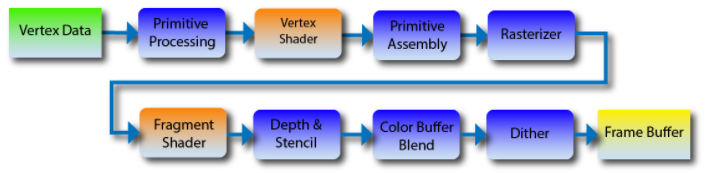
The used pipeline is similiar to OpenGL 2 and therefore only fragment and vertex shaders. In newer versions of OpenGL there are other shaders, e.g. to generate geometry on the fly.
Vertex Shader
The main goal of the vertex shader is to transform the coordinates of the vertices. The secondary goal is to prepare data for the fragment shader.
Gouraud Shader As Example
1
2
3
4
5
6
7
8
9
10
11
12
13
14
struct GouraudShader : public IShader
{
    Vec3f varying_intensity; // written by vertex shader, read by fragment shader

    virtual Vec4f vertex(int iface, int nthvert) {
        // get diffuse lighting intensity
        varying_intensity[nthvert] = std::max(0.f, model->normal(iface, nthvert) * light_dir);
        // read the vertex from .obj file
        Vec4f gl_Vertex = embed<4>(model->vert(iface, nthvert));
        //transform it to screen coordinates
        return Viewport * Projection * ModelView * gl_Vertex;
    }

    // continued in fragment shader
varying is a reserved keyword in GLSL language. In varying variables we store data to be interpolated inside the triangle, and the fragment shaders get the interpolated values (for current pixel).
uniform is a reserved keyword in GLSL, it allows to pass constants to the shaders.
Rasterizer
The rasterizer calls the routine of the fragment shader for each pixel.
Z-Buffer
By means of Barycentric Coordinates the depth position of every pixel can be calculated. From the 1-dimensional situation it is possible to understand the 3D:
1
2
int y = p0.y*(1.-t) + p1.y*t;
// where y is the depth coord
It turns out that are barycentric coordinates of the point with respect to the segment : . So the idea is to take the barycentric coordinates version of triangle rasterization, and for every pixel we want to draw simply to multiply its barycentric coordinates by the z-values of the vertices of the triangle we rasterize.
Finally the z-Buffer value has to be calculated by dividing by the 4th coordinate in barycentric coordinates.
1
2
3
4
Vec3f c = barycentric(proj<2>(pts[0] / pts[0][3]), proj<2>(pts[1] / pts[1][3]), proj<2>(pts[2] / pts[2][3]), P /*proj<2>(P)*/);
float z = pts[0][2] * c.x + pts[1][2] * c.y + pts[2][2] * c.z;
float w = pts[0][3] * c.x + pts[1][3] * c.y + pts[2][3] * c.z;
int frag_depth = std::max(0, std::min(255, int(z / w + .5)));
Fragment Shader
The main goal of the fragment shader is to determine the color of the current pixel. The secondary goal is to discard current pixel by returning true.
Gouraud Shader As Example
1
2
3
4
5
6
7
8
9
10
11
12
    // written by vertex shader, read by fragment shader
    // [...]
    Vec3f varying_intensity;
    virtual bool fragment(Vec3f bar, TGAColor &color) {
        // interpolate intensity for the current pixel
        float intensity = varying_intensity * bar;
        // calculate current color
        color = TGAColor(255, 255, 255) * intensity;
        // no, we do not discard this pixel
        return false;
    }
};
In this example the fragment shaders computes the interpolated intensity. In true GLSL, of course, fragment shaders receive ready interpolated values.
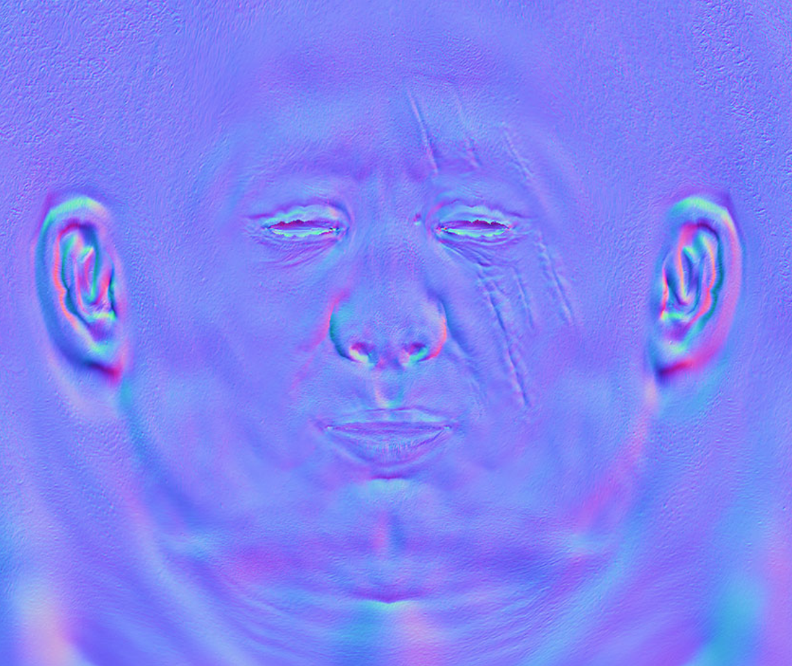
Normal Mapping
The normal of each vertex can be stored in a normal map using the RGB values as xyz directions.
Normally they are stored in Darboux frame. In Darboux frame the coordinate system is aligned so that the z-vector is normal to the object, x the principal curvature direction and y their cross product. Due to this coordinate system it is a local coordinate system per vertices. We have therefore to map it to the global coordinate system to use with f.ex. lightning, but in case of animations this helps massively. We can also reduce the normal map of symmetric objects to the half.
Transformation Of Normal Vectors
If we have a model and its normal vectors are given by the artist AND this model is transformed with an affine mapping, then normal vectors are to be transformed with a mapping, equal to the transposition of the inverse matrix of the original mapping matrix.
If we transfrom a fragment, we can not just transform the normal vector with the same transformation. We need to compute new normal vectors to the transformed fragment.
Phong Reflection Model
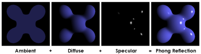
This is a local illumination model. In other words, computing illumination of a current pixel doesn’t take into account its neighbors.
In this model the final illumination for a point is the sum of three components: ambient intensitity (constant for all points in the scene), diffuse and specular highlights (depending on normal vectors).
Reflected Light
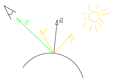
For Diffuse Lighting we take the dot product of vector and . This amount is used to calculate the final diffuse lighting.
For specular lighting we compute the (cosine of) angle between vectors n and l. We walk twice this amount in the direction of and subtract the vector to get the reflection vector .
The amount of Specular Light calculated by the z-componented of the reflected light vector and the value per pixel from the specular map.
1
float spec = pow(std::max(r.z, 0.f), model->specular(uv));
Shadow Mapping
There are two different shadow mappings, hard shadow and soft shadow. In case of hard shadow, there is only one light source which results in a clear outline of the shadow. While in soft shadow mapping the light source is thought of not concentrated in a single point on therefore the shadow results in a blurred out area specially at the farther corners of it.
Two-Pass Rendering
The achieve a hard shadow mapping we will do a two-pass rendering.
First time we will render the image placing the camera at the light source position. It will allow to determine what parts are lit and what parts are hidden from the light. The result is written into the depth buffer.
Then in the second pass we do a render taking in account the visibility information.
Ambient Occlusion
Why to choose a constant ambient component? There are other possibilities to simulate a more accurate diffuse lighting.
Brute Force Approach
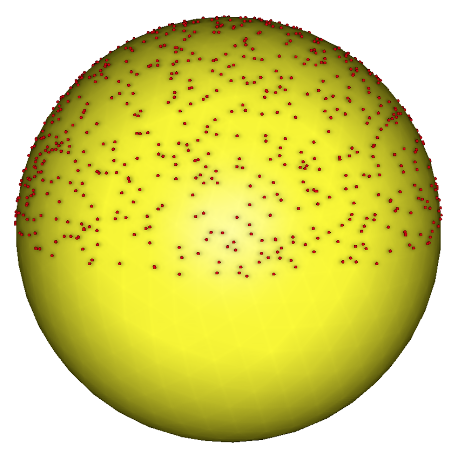
Choose an arbituary amount of light sources on a (hemi-)sphere. Use this light sources as eye point a calculate the z-buffer from this point of view. All pixels which are seeing from every eye point are drawn white into an occlusion mask. This mask is defined in the uv space similar to the diffusion mask. Summing up these occlusion masks leads to the total ambient occlusion mask of the object.
Screen Space Ambient Occlusion
The brute force approach is an expensive thing, it requires visibility computations for many points. Let’s find a compromise between computing time and rendering quality.
Introducing a Post-Processing Routine
While the shader only computes the z-buffer the post-processing routine will calculate the pixel’s color value.
In the post-processing, we emit a number of rays in all directions around the pixel. The z-buffer is used as a height map. We want to compute the slope in each direction from the current pixel.
In theory we need to compute the solid angle for each point of the z-buffer. The solid angle can be approximated by .
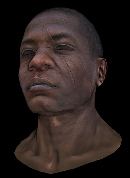
Final Image